After the last post there was only one topic left on my list: The Trace() function. Initially it seemed like a quick and easy task to summarize my findings, the work was already done… but as with most things it kept getting longer as I was working on it.

I hope you’re still ready to follow along — this one takes a rather meandering tour around vector maths and trigonometry and being well rested seems advisable for my various musings.


This is the fourth in a series of posts:

— Overview —

Ah, and there’s also bit of a valley of despair in the middle. But I’ll provide a handy shortcut to skip all that, no worries.

Well, off we go. One last function to tackle!

— Function: Trace —

 1
 2
 3
 4
 5
 6
 7
 8
 9
10
11
12
13
14
15
16
17
18
19
20
21
22
23
24
25
26
27
28
29
30
31
32
33
34
35
36
37
38
39
40
41
42
43
44
45
46
47

Vector3 Trace(Vector3 origin, Vector3 direction) {
    Vector3 sampledPosition(1, 1, 1);
    Vector3 normal(1, 1, 1);
    Vector3 color(0, 0, 0);
    Vector3 attenuation(1, 1, 1);
    Vector3 lightDirection(light_direction); // Directional light
    lightDirection.Normalize();

    for (int bounceCount = 3; bounceCount--;) {
        int hitType = RayMarching(origin, direction, sampledPosition, normal);
        if (hitType == HIT_NONE) break; // No hit. This is over, return color.
        if (hitType == HIT_LETTER) { // Specular bounce on a letter. No color acc.
            direction = direction + normal * ( normal.DotProduct(direction) * -2);
            origin = sampledPosition + direction * 0.1;
            attenuation = attenuation * 0.2; // Attenuation via distance traveled.
        }
        if (hitType == HIT_WALL) { // Wall hit uses color yellow?
            float incidence = normal.DotProduct(lightDirection);
            float p = 6.283185 * randomVal();
            float c = randomVal();
            float s = sqrtf(1 - c);
            float g = normal.z_ < 0 ? -1 : 1;
            float u = -1 / (g + normal.z_);
            float v = normal.x_ * normal.y_ * u;
            direction = Vector3(v,
                          g + normal.y_ * normal.y_ * u,
                          -normal.y_) * (cosf(p) * s)
                      +
                      Vector3(1 + g * normal.x_ * normal.x_ * u,
                          g * v,
                          -g * normal.x_) * (sinf(p) * s) + normal * sqrtf(c);
            origin = sampledPosition + direction * .1;
            attenuation = attenuation * 0.2;
            if (incidence > 0 &&
                 RayMarching(sampledPosition + normal * .1,
                             lightDirection,
                             sampledPosition,
                             normal) == HIT_SUN)
                color = color + attenuation * Vector3(500, 400, 100) * incidence;
        }
        if (hitType == HIT_SUN) { //
          color = color + attenuation * Vector3(50, 80, 100); break; // Sun Color
        }
    }
    return color;
}

Here’s what Trace() looks like right now. It takes as arguments two vectors, an origin to start from and a direction to trace in. The function itself is pretty straight-forward too:

  1. Loop for a fixed amount of bounces/reflections of our ray (line 10)
  2. Call RayMarching with the current origin + direction, which yields sampledPosition and normal as vectors, and the hitType
  3. Based on the type of object hit, alter the return color and calculate a new direction, or exit:
    • on HIT_NONE (line 12): Just return, this ray ends here. Nothing was hit so there isn’t really anywhere to go from here.
    • on HIT_LETTER (line 13+): Reflect direction vector off the plane defined by the normal vector. New origin is slightly offset from sampledPosition to not get stuck. Attenuate ( = dim color with every reflect, basically).
    • on HIT_WALL (line 18+): Uhhhhh… err. Yeah. Look at the code. We are… doing what exactly here?? Some absolutely wild float variable juggling to get a new direction. This’ll be our focus today. Then, once again offset new position, attenuate… and alter sample color if we can HIT_SUN in lightDirection, i.e. if surface is in direct sunlight.
    • on HIT_SUN (line 42): Add attenuated sunlight color and return.

So some basic observations:

  • only breaks on HIT_NONE or HIT_SUN, although of course we’re also limited by max. reflections.
  • on the other cases we reduce attenuation by 80% which starts out as (1.0, 1.0, 1.0). So if we hit the light right away on first march, we get the full sunlight color. If we hit light after bouncing off one thing, we get 0.2 or 20% of the sunlight. If we bounce twice, we get \(0.2^2 = 0.04\) or 4% of the light, and so on…
  • Interestingly enough, the light color of the sun, and by extension the color of the scene is a bluish tone, and the warm color is contributed by the walls that are directly illuminated by sunlight.

New direction on HIT_WALL

Now, this snippet below is what we’re digging into, so I want you to take a good look at it and try to figure out what’s going on for yourself. I took it as a puzzle that I could rewrite as something that looks logical and legible. Once you’re satisfied with your own puzzlement, follow along.

 1
 2
 3
 4
 5
 6
 7
 8
 9
10
11
12
13
14
15
16
17
18
19
20
21
22
23
24
if (hitType == HIT_WALL) { // Wall hit uses color yellow?
    float incidence = normal.DotProduct(lightDirection);
    float p = 6.283185 * randomVal();
    float c = randomVal();
    float s = sqrtf(1 - c);
    float g = normal.z_ < 0 ? -1 : 1;
    float u = -1 / (g + normal.z_);
    float v = normal.x_ * normal.y_ * u;
    direction = Vector3(v,
                  g + normal.y_ * normal.y_ * u,
                  -normal.y_) * (cosf(p) * s)
             +
             Vector3(1 + g * normal.x_ * normal.x_ * u,
                  g * v,
                  -g * normal.x_) * (sinf(p) * s) + normal * sqrtf(c);
    origin = sampledPosition + direction * .1;
    attenuation = attenuation * 0.2;
    if (incidence > 0 &&
         RayMarching(sampledPosition + normal * .1,
                     lightDirection,
                     sampledPosition,
                     normal) == HIT_SUN)
        color = color + attenuation * Vector3(500, 400, 100) * incidence;
}

I was certainly very stumped on this when I first saw it. I was more than a bit rusty on my trigonometry as well.

The big picture

First off, let’s get our bearings. The first local variable incidence is just the dot product of the hit normal and lightDirection. The latter is a unit vector that actually points towards the light - it is the inverse of the direction the light would be traveling in.

$$\mathbf{a}\cdot\mathbf{b}=\|\mathbf{a}\|\ \|\mathbf{b}\|\cos\theta$$

Going by the geometric definition of the dot product, we can drop the magnitudes/lengths since they’re 1, and incidence is just the cosine of the angle between the vectors. At a right angle it is 0.0f. If they’re exactly the same direction (identical, even) the value is 1.0f, if they point in opposite directions it’s -1.0f.

Towards the end of the snippet we do the usual bits of setting origin to a point slightly offset from sampledPosition and updating the attenuation.

Then we have the first use of incidence: If it’s above zero, i.e. the angle between normal & light vector is less than \(90^\circ\), which in turn means the surface is actually facing the light, then we do a RayMarching check from sampledPosition along lightDirection to see if we hit the sun. If we do, we’re in direct sunlight and alter the color.

That’s the easy bits out of the way. Let’s look at the “inputs” and “outputs” of the highlighted code. A lot of the single letter variables are obviously just local helper vars, the only thing we’re really getting “out” of this is direction. And we’re doing that based on the normal vector and two randomly generated floats between 0.0 - 1.0. Curiouser and curiouser!

Another assumption I was fairly certain of: The code is taking some “shortcuts” or doing things within the constraint of our normal vector on the walls always pointing along one of the three axes. So this code only works if \(normal \in \{({\footnotesize\pm}1, 0, 0), (0, {\footnotesize\pm}1, 0), (0, 0, {\footnotesize\pm}1)\}\).

But really, I had no clue what I was looking at, when I began puzzling. So I just started experimenting, trying to express things differently and check if the code still does what it should. My experimentation wasn’t exactly methodical though - it was more haphazard futzing about. I’m ashamed to admit I didn’t even version control it, I just kinda commented out the previous code, messed around a bit, and then duplicated it again after a while to leave a trail of changes… the worst kind of version controlled code from someone who didn’t want to commit (pun intended) to creating a git repo and doing things properly. I just wanted to hack around in my code editor.

Only afterwards it occurred to me, that I could write blog posts about it and detail what I’d found out. And then I only worked on these sporadically, and now here I am, almost a year later, and I’ll try to reconstruct my line of thinking :)

Going in circles

Here’s my first iteration:

 1
 2
 3
 4
 5
 6
 7
 8
 9
10
11
12
13
14
15
16
17
18
19
20
21
22
23
24
25
26
27
28
29
30
          float p = 6.283185 * Urho3D::Random(0.0f, 1.0f);

          float c = Urho3D::Random(0.0f, 1.0f);
          float s = 1.0f - c;
          c = sqrtf(c);
          s = sqrtf(s);

            float n_down = normal.z_ < 0 ? -1 : 1;

            float u;
            if(normal.z_ < 0) {
                u = -1 / (normal.z_ - 1.0f);
            } else {
                u = -1 / (normal.z_ + 1.0f);
            }

            float dir_x, dir_y, dir_z;
            dir_x = (         normal.x_ * normal.y_ * u) * (cosf(p) * s)
            dir_y = (n_down + normal.y_ * normal.y_ * u) * (cosf(p) * s)
            dir_z = (       - normal.y_                ) * (cosf(p) * s)

            dir_x += (1 + n_down * normal.x_ * normal.x_ * u) * (sinf(p) * s)
            dir_y += (    n_down * normal.x_ * normal.y_ * u) * (sinf(p) * s)
            dir_z -= (  - n_down * normal.x_                ) * (sinf(p) * s)

            dir_x += normal.x_ * sqrtf(c);
            dir_y += normal.y_ * sqrtf(c);
            dir_z += normal.z_ * sqrtf(c);

          direction = Vector3(dir_x, dir_y, dir_z);

…or something along these lines. Actually at this stage my direction = Vector3(...) was still the singular long line, and later dir_x, dir_y and dir_z got assigned their complete value straight away. I’ve decided to break those into three distinct blocks now, because now the three blocks are stacked vertically instead of being stacked horizontally forming very long lines. I hope that makes sense.

Besides that, what else happened? I started using Urho’s Random, but outside of that float p is unchanged. Same goes for float c. It seems p is some sort of angle between 0 and \(2\pi=360^\circ\). It’s hard to tell what c and s might be, but since \(\sin{45^\circ} = \cos{45^\circ} = \frac{\sqrt{2}}{2}\) I thought maybe this is a very roundabout way of approximating the sine & cosine of an angle? I was thinking somewhere along those lines, however much sense that may or may not actually make.

I renamed float g to n_down, since it is -1 for any normal vector pointing downwards and 1 for all the others. I made float u based around an if-statement independent of the former, to see if that’d get me any more clarity. I don’t believe it did.

And in the construction of the final vector, I was trying to see if I could pull out anything like a cross product or rotational matrix or anything that’d look familiar and had just gotten reduced.

For example we did have variables named u & v, which could look like texture coordinates or something of the sort, but I actually assimilated v into the calculations, since its value lined up so nicely with the other components.


Spoiler alert: The stuff I’m about to detail here didn’t really get me anywhere, other than closer to going proper mad. Feel free to skip to the next section “Back To Basics to see a clear solution to what’s up with the calculations I’m about to butcher!

(Also, double click anywhere on code blocks to fold/unfold them quickly!)


I pushed through further iterations:

 1
 2
 3
 4
 5
 6
 7
 8
 9
10
11
12
13
14
15
16
17
18
19
20
21
22
23
24
25
26
27
28
29
30
31
32
33
34
35

		float angle_a = 6.283185 * Urho3D::Random(0.0f, 1.0f);
		float angle_b = 6.283185 * Urho3D::Random(0.0f, 1.0f);


		angle_a /= 4;
		float cos_a = cosf(angle_a);
		float sin_a = sinf(angle_a);

		float cos_b = cosf(angle_b);
		float sin_b = sinf(angle_b);

		float n_down = normal.z_ < 0 ? -1 : 1;

		float u;
		if(normal.z_ < 0) {
			u = -1 / (normal.z_ - 1.0f);
		} else {
			u = -1 / (normal.z_ + 1.0f);
		}

      float dir_x, dir_y, dir_z;
      dir_x = (         normal.y_ * normal.x_ * u) * (cos_b * sin_a)
      dir_y = (n_down + normal.y_ * normal.y_ * u) * (cos_b * sin_a)
      dir_z = (       - normal.y_                ) * (cos_b * sin_a)

      dir_x += (1 + n_down * normal.x_ * normal.x_ * u) * (sin_b * sin_a)
      dir_y += (    n_down * normal.x_ * normal.y_ * u) * (sin_b * sin_a)
      dir_z -= (  - n_down * normal.x_                ) * (sin_b * sin_a)

      dir_x += normal.x_ * cos_a;
      dir_y += normal.y_ * cos_a;
      dir_z += normal.z_ * cos_a;

      direction = Vector3(dir_x, dir_y, dir_z);

angle_b is what used to be p, and angle_a is for cos_a and sin_a which are now in place of c & s.

From here on out these angle_ and cos_/sin_-variables are used in every snippet, so I didn’t include their definitions in each. They’re still used throughout, without changes.

 1
 2
 3
 4
 5
 6
 7
 8
 9
10
11
12
13
14
15
16
17
18
19
20
21
22
23
24
25
26
27
28
29
30
31
32
33
34
35
      //[...]

		float u;
      float dir_x, dir_y, dir_z;

      if(normal.z_ < 0) {
         u = 1 / (normal.z_ - 1.0f);

         dir_x = (    - normal.y_ * normal.x_ * u) * (cos_b * sin_a);
         dir_y = ( -1 - normal.y_ * normal.y_ * u) * (cos_b * sin_a);
         dir_z = (    - normal.y_                ) * (cos_b * sin_a);

         dir_x +=  ( 1 + normal.x_ * normal.x_ * u) * (sin_b * sin_a);
         dir_y +=  (     normal.x_ * normal.y_ * u) * (sin_b * sin_a);
         dir_z +=  (     normal.x_                ) * (sin_b * sin_a);

         dir_x += normal.x_ * cos_a;
         dir_y += normal.y_ * cos_a;
         dir_z += normal.z_ * cos_a;
      } else {
         u = 1 / (normal.z_ + 1.0f);

         dir_x = (    - normal.y_ * normal.x_ * u) * (cos_b * sin_a);
         dir_y = (  1 - normal.y_ * normal.y_ * u) * (cos_b * sin_a);
         dir_z = (    - normal.y_                ) * (cos_b * sin_a);

         dir_x +=  ( 1 - normal.x_ * normal.x_ * u) * (sin_b * sin_a);
         dir_y +=  (   - normal.x_ * normal.y_ * u) * (sin_b * sin_a);
         dir_z +=  (   - normal.x_                ) * (sin_b * sin_a);

         dir_x += normal.x_ * cos_a;
         dir_y += normal.y_ * cos_a;
         dir_z += normal.z_ * cos_a;
      }
      direction = Vector3(dir_x, dir_y, dir_z);

I split things into two chunks of calculations based on the normal.z < 0 condition. Doing that I eliminated n_down. I also introduced x_vec and y_vec hoping those would help me find something where the zeroes of certain vectors had been dropped? Maybe?

 1
 2
 3
 4
 5
 6
 7
 8
 9
10
11
12
13
14
15
16
17
18
19
20
21
22
23
24
25
26
27
28
29
30
31
32
33
34
35
36
37
38
      //[...]

		float u;
      float dir_x, dir_y, dir_z;

      Vector3 x_vec = Vector3(1, 0, 0);
      Vector3 y_vec = Vector3(0, 1, 0);

      if(normal.z_ < 0) {
         u = 1 / (normal.z_ - 1.0f);

         dir_x = (  y_vec.x - normal.y_ * normal.x_ * u) * (cos_b * sin_a);
         dir_y = ( -y_vec.y - normal.y_ * normal.y_ * u) * (cos_b * sin_a);
         dir_z = (  y_vec.z - normal.y_                ) * (cos_b * sin_a);

         dir_x +=  ( x_vec.x + normal.x_ * normal.x_ * u) * (sin_b * sin_a);
         dir_y +=  ( x_vec.y + normal.x_ * normal.y_ * u) * (sin_b * sin_a);
         dir_z +=  ( x_vec.z + normal.x_                ) * (sin_b * sin_a);

         dir_x += normal.x_ * cos_a;
         dir_y += normal.y_ * cos_a;
         dir_z += normal.z_ * cos_a;
      } else {
         u = 1 / (normal.z_ + 1.0f);

         dir_x = (  y_vec.x - normal.y_ * normal.x_ * u) * (cos_b * sin_a);
         dir_y = (  y_vec.y - normal.y_ * normal.y_ * u) * (cos_b * sin_a);
         dir_z = (  y_vec.z - normal.y_                ) * (cos_b * sin_a);

         dir_x +=  ( x_vec.x - normal.x_ * normal.x_ * u) * (sin_b * sin_a);
         dir_y +=  ( x_vec.y - normal.x_ * normal.y_ * u) * (sin_b * sin_a);
         dir_z +=  ( x_vec.z - normal.x_                ) * (sin_b * sin_a);

         dir_x += normal.x_ * cos_a;
         dir_y += normal.y_ * cos_a;
         dir_z += normal.z_ * cos_a;
      }
      direction = Vector3(dir_x, dir_y, dir_z);

I even turned it into three cases with the assumption that \(\texttt{normal.z} \in \{-1, 0, 1\}\), which at least seems to hold for everything that is rendered with this, which is only the walls of the boxes.

 1
 2
 3
 4
 5
 6
 7
 8
 9
10
11
12
13
14
15
16
17
18
19
20
21
22
23
24
25
26
27
28
29
30
31
32
33
34
35
36
37
38
39
40
41
42
43
44
		//[...]
      float dir_x, dir_y, dir_z;

      Vector3 x_vec = Vector3(1, 0, 0);
      Vector3 y_vec = Vector3(0, 1, 0);

		if(normal.z_ < -0.000001f) { // Ceiling
         dir_x = (  y_vec.x - normal.y_ * normal.x_ / normal.z_ + normal.y_ * normal.x_) * (cos_b * sin_a);
         dir_y = ( -y_vec.y - normal.y_ * normal.y_ / normal.z_ + normal.y_ * normal.y_) * (cos_b * sin_a);
         dir_z = (  y_vec.z - normal.y_                                                ) * (cos_b * sin_a);

         dir_x += ( x_vec.x + normal.x_ * normal.x_ / normal.z_ - normal.x_ * normal.x_) * (sin_b * sin_a);
         dir_y += ( x_vec.y + normal.x_ * normal.y_ / normal.z_ - normal.x_ * normal.y_) * (sin_b * sin_a);
         dir_z += ( x_vec.z + normal.x_                                                ) * (sin_b * sin_a);

         dir_x += normal.x_ * cos_a;
         dir_y += normal.y_ * cos_a;
         dir_z += normal.z_ * cos_a;
      } else if(normal.z_ >  0.000001f) { // Floor
         dir_x = (  y_vec.x - normal.y_ * normal.x_ / normal.z_ - normal.y_ * normal.x_) * (cos_b * sin_a);
         dir_y = (  y_vec.y - normal.y_ * normal.y_ / normal.z_ - normal.y_ * normal.y_) * (cos_b * sin_a);
         dir_z = (  y_vec.z - normal.y_                                                ) * (cos_b * sin_a);

         dir_x += ( x_vec.x - normal.x_ * normal.x_ / normal.z_ - normal.x_ * normal.x_) * (sin_b * sin_a);
         dir_y += ( x_vec.y - normal.x_ * normal.y_ / normal.z_ - normal.x_ * normal.y_) * (sin_b * sin_a);
         dir_z += ( x_vec.z - normal.x_                                                ) * (sin_b * sin_a);

         dir_x += normal.x_ * cos_a;
         dir_y += normal.y_ * cos_a;
         dir_z += normal.z_ * cos_a;
      } else { // Wall, z=0 => u=1
         dir_x = (  y_vec.x - normal.y_ * normal.x_) * (cos_b * sin_a);
         dir_y = (  y_vec.y - normal.y_ * normal.y_) * (cos_b * sin_a);
         dir_z = (  y_vec.z - normal.y_            ) * (cos_b * sin_a);

         dir_x += ( x_vec.x - normal.x_ * normal.x_) * (sin_b * sin_a);
         dir_y += ( x_vec.y - normal.x_ * normal.y_) * (sin_b * sin_a);
         dir_z += ( x_vec.z - normal.x_            ) * (sin_b * sin_a);

         dir_x += normal.x_ * cos_a;
         dir_y += normal.y_ * cos_a;
         dir_z += normal.z_ * cos_a;
      }
      direction = Vector3(dir_x, dir_y, dir_z);

I switched the position of the sin/sin & cos/sin block and inverted some stuff. I guess?

 1
 2
 3
 4
 5
 6
 7
 8
 9
10
11
12
13
14
15
16
17
18
19
20
21
22
23
24
25
26
27
28
29
30
31
32
33
34
35
36
37
38
39
40
41
42
43
44
45
46
47
48
49
50
51
      //[...]
      float dir_x, dir_y, dir_z;

      Vector3 x_vec = Vector3(1, 0, 0);
      Vector3 y_vec = Vector3(0, 1, 0);

		if(normal.z_ < -0.000001f) { // Ceiling
         dir_x = - ( - x_vec.x - normal.x_ * normal.x_ / normal.z_ + normal.x_ * normal.x_) * (sin_b * sin_a);
         dir_y = - ( - x_vec.y - normal.x_ * normal.y_ / normal.z_ + normal.x_ * normal.y_) * (sin_b * sin_a);
         dir_z =   (   x_vec.z + normal.x_                                                ) * (sin_b * sin_a);

         dir_x += (  y_vec.x - normal.y_ * normal.x_ / normal.z_ + normal.y_ * normal.x_) * (cos_b * sin_a);
         dir_y += ( -y_vec.y - normal.y_ * normal.y_ / normal.z_ + normal.y_ * normal.y_) * (cos_b * sin_a);
         dir_z += (  y_vec.z - normal.y_                                                ) * (cos_b * sin_a);

         dir_x += normal.x_ * cos_a;
         dir_y += normal.y_ * cos_a;
         dir_z += normal.z_ * cos_a;

         direction = Vector3(dir_x, dir_y, dir_z);

      } else if(normal.z_ >  0.000001f) { // Floor
         dir_x = - ( x_vec.x - normal.x_ * normal.x_ / normal.z_ - normal.x_ * normal.x_) * (sin_b * sin_a);
         dir_y = - ( x_vec.y - normal.x_ * normal.y_ / normal.z_ - normal.x_ * normal.y_) * (sin_b * sin_a);
         dir_z = - ( x_vec.z - normal.x_                                                ) * (sin_b * sin_a);

         dir_x -= (  y_vec.x - normal.y_ * normal.x_ / normal.z_ - normal.y_ * normal.x_) * (cos_b * sin_a);
         dir_y -= (  y_vec.y - normal.y_ * normal.y_ / normal.z_ - normal.y_ * normal.y_) * (cos_b * sin_a);
         dir_z -= (  y_vec.z - normal.y_                                                ) * (cos_b * sin_a);

         dir_x -= normal.x_ * cos_a;
         dir_y -= normal.y_ * cos_a;
         dir_z -= normal.z_ * cos_a;

         direction = Vector3(-dir_x, -dir_y, -dir_z);

      } else { // Wall, z=0 => u=1
         dir_x = - ( x_vec.x - normal.x_ * normal.x_) * (sin_b * sin_a);
         dir_y = - ( x_vec.y - normal.x_ * normal.y_) * (sin_b * sin_a);
         dir_z = - ( x_vec.z - normal.x_            ) * (sin_b * sin_a);

         dir_x -= (  y_vec.x - normal.y_ * normal.x_) * (cos_b * sin_a);
         dir_y -= (  y_vec.y - normal.y_ * normal.y_) * (cos_b * sin_a);
         dir_z -= (  y_vec.z - normal.y_            ) * (cos_b * sin_a);

         dir_x -= normal.x_ * cos_a;
         dir_y -= normal.y_ * cos_a;
         dir_z -= normal.z_ * cos_a;

         direction = Vector3(-dir_x, -dir_y, -dir_z);
      }

I removed x_vec and y_vec again because I wasn’t really seeing anything useful with them. The -= normal.z * cos_a is now after the conditionals because it’s the same across all variations.

 1
 2
 3
 4
 5
 6
 7
 8
 9
10
11
12
13
14
15
16
17
18
19
20
21
22
23
24
25
26
27
28
29
30
31
32
33
34
35
36
		//[...]
      float dir_x, dir_y, dir_z;

		if(normal.z_ < -0.000001f) { // Ceiling
         dir_x = ( -1 - normal.x_ * normal.x_ / normal.z_ + normal.x_ * normal.x_) * sin_b * sin_a;
         dir_y = (    - normal.x_ * normal.y_ / normal.z_ + normal.x_ * normal.y_) * sin_b * sin_a;
         dir_z =      - normal.x_                                                  * sin_b * sin_a;

         dir_x -= (    - normal.y_ * normal.x_ / normal.z_ + normal.y_ * normal.x_) * cos_b * sin_a;
         dir_y -= ( -1 - normal.y_ * normal.y_ / normal.z_ + normal.y_ * normal.y_) * cos_b * sin_a;
         dir_z +=        normal.y_                                                  * cos_b * sin_a;

      } else if(normal.z_ >  0.000001f) { // Floor
         dir_x = - ( 1 - normal.x_ * normal.x_ / normal.z_ - normal.x_ * normal.x_) * sin_b * sin_a;
         dir_y = - (   - normal.x_ * normal.y_ / normal.z_ - normal.x_ * normal.y_) * sin_b * sin_a;
         dir_z =         normal.x_                                                  * sin_b * sin_a;

         dir_x -= (   - normal.y_ * normal.x_ / normal.z_ - normal.y_ * normal.x_) * cos_b * sin_a;
         dir_y -= ( 1 - normal.y_ * normal.y_ / normal.z_ - normal.y_ * normal.y_) * cos_b * sin_a;
         dir_z +=       normal.y_                                                  * cos_b * sin_a;

      } else { // Wall, z=0 => u=1
         dir_x = - ( 1 - normal.x_ * normal.x_) * sin_b * sin_a;
         dir_y =         normal.x_ * normal.y_  * sin_b * sin_a;
         dir_z =         normal.x_              * sin_b * sin_a;

         dir_x -= (   - normal.y_ * normal.x_) * cos_b * sin_a;
         dir_y -= ( 1 - normal.y_ * normal.y_) * cos_b * sin_a;
         dir_z +=       normal.y_              * cos_b * sin_a;
      }

      dir_x -= normal.x_ * cos_a;
      dir_y -= normal.y_ * cos_a;
      dir_z -= normal.z_ * cos_a;

      direction = Vector3(-dir_x, -dir_y, -dir_z);

I cleared out the negations and uses of -= in the “Floor” case.

 1
 2
 3
 4
 5
 6
 7
 8
 9
10
11
12
13
14
15
16
17
18
19
20
21
22
23
24
25
26
27
28
29
30
31
32
33
34
35
36
		//[...]
      float dir_x, dir_y, dir_z;

		if(normal.z_ < -0.000001f) { // Ceiling
         dir_x = ( -1 - normal.x_ * normal.x_ / normal.z_ + normal.x_ * normal.x_) * sin_b * sin_a;
         dir_y = (    - normal.x_ * normal.y_ / normal.z_ + normal.x_ * normal.y_) * sin_b * sin_a;
         dir_z =      - normal.x_                                                  * sin_b * sin_a;

         dir_x -= (    - normal.y_ * normal.x_ / normal.z_ + normal.y_ * normal.x_) * cos_b * sin_a;
         dir_y -= ( -1 - normal.y_ * normal.y_ / normal.z_ + normal.y_ * normal.y_) * cos_b * sin_a;
         dir_z +=        normal.y_                                                  * cos_b * sin_a;

      } else if(normal.z_ >  0.000001f) { // Floor
         dir_x = ( -1 + normal.x_ * normal.x_ / normal.z_ + normal.x_ * normal.x_) * sin_b * sin_a;
         dir_y = (    + normal.x_ * normal.y_ / normal.z_ + normal.x_ * normal.y_) * sin_b * sin_a;
         dir_z =        normal.x_                                                  * sin_b * sin_a;

         dir_x += (      normal.y_ * normal.x_ / normal.z_ + normal.y_ * normal.x_) * cos_b * sin_a;
         dir_y += ( -1 + normal.y_ * normal.y_ / normal.z_ + normal.y_ * normal.y_) * cos_b * sin_a;
         dir_z +=        normal.y_                                                  * cos_b * sin_a;

      } else { // Wall, z=0 => u=1
         dir_x = ( normal.x_ * normal.x_ - 1) * sin_b * sin_a;
         dir_y =   normal.x_ * normal.y_      * sin_b * sin_a;
         dir_z =   normal.x_                  * sin_b * sin_a;

         dir_x += ( normal.y_ * normal.x_     ) * cos_b * sin_a;
         dir_y += ( normal.y_ * normal.y_ - 1 ) * cos_b * sin_a;
         dir_z +=   normal.y_                   * cos_b * sin_a;
      }

      dir_x -= normal.x_ * cos_a;
      dir_y -= normal.y_ * cos_a;
      dir_z -= normal.z_ * cos_a;

      direction = Vector3(-dir_x, -dir_y, -dir_z);

I pulled the common uses of normal.x and normal.y out, because commutative multiplications.

 1
 2
 3
 4
 5
 6
 7
 8
 9
10
11
12
13
14
15
16
17
18
19
20
21
22
23
24
25
26
27
28
29
30
31
32
33
34
35
36
		//[...]
      float dir_x, dir_y, dir_z;

		if(normal.z_ < -0.000001f) { // Ceiling
         dir_x = ( normal.x_ * ( normal.x_ - normal.x_ / normal.z_ ) - 1 ) * sin_b * sin_a;
         dir_y = ( normal.x_ * ( normal.y_ - normal.y_ / normal.z_ )     ) * sin_b * sin_a;
         dir_z = - normal.x_                                               * sin_b * sin_a;

         dir_x -= ( normal.y_ * ( normal.x_ - normal.x_ / normal.z_ )     ) * cos_b * sin_a;
         dir_y -= ( normal.y_ * ( normal.y_ - normal.y_ / normal.z_ ) - 1 ) * cos_b * sin_a;
         dir_z +=   normal.y_                                               * cos_b * sin_a;

      } else if(normal.z_ >  0.000001f) { // Floor
         dir_x = ( normal.x_ * ( normal.x_ / normal.z_ + normal.x_ ) - 1 ) * sin_b * sin_a;
         dir_y = ( normal.x_ * ( normal.y_ / normal.z_ + normal.y_ )     ) * sin_b * sin_a;
         dir_z =   normal.x_                                               * sin_b * sin_a;

         dir_x += ( normal.y_ * ( normal.x_ / normal.z_ + normal.x_ )     ) * cos_b * sin_a;
         dir_y += ( normal.y_ * ( normal.y_ / normal.z_ + normal.y_ ) - 1 ) * cos_b * sin_a;
         dir_z +=   normal.y_                                               * cos_b * sin_a;

      } else { // Wall, z=0 => u=1
         dir_x = ( normal.x_ * normal.x_ - 1) * sin_b * sin_a;
         dir_y =   normal.x_ * normal.y_      * sin_b * sin_a;
         dir_z =   normal.x_                  * sin_b * sin_a;

         dir_x += ( normal.y_ * normal.x_     ) * cos_b * sin_a;
         dir_y += ( normal.y_ * normal.y_ - 1 ) * cos_b * sin_a;
         dir_z +=   normal.y_                   * cos_b * sin_a;
      }

      dir_x -= normal.x_ * cos_a;
      dir_y -= normal.y_ * cos_a;
      dir_z -= normal.z_ * cos_a;

      direction = Vector3(-dir_x, -dir_y, -dir_z);

I took the instances where there’s a - 1 in the brackets somewhere and pulled it out, which results in the lines like dir_x -= sin_b * sin_a;. In my actual working out from back then I believe I made a mistake somewhere, which gave me all subtractions across all cases, which unfortunately doesn’t even seem to be correct. I have no clue if this is still all equivalent to the original code, but it seemed to still be giving the same output.

 1
 2
 3
 4
 5
 6
 7
 8
 9
10
11
12
13
14
15
16
17
18
19
20
21
22
23
24
25
26
27
28
29
30
31
32
33
34
35
36
37
38
39
40
41
42
43
44
45
		//[...]
      float dir_x, dir_y, dir_z;

		if(normal.z_ < -0.000001f) { // Ceiling
         dir_x =   normal.x_ * ( normal.x_ - normal.x_ / normal.z_ ) * sin_b * sin_a;
         dir_y =   normal.x_ * ( normal.y_ - normal.y_ / normal.z_ ) * sin_b * sin_a;
         dir_z = - normal.x_                                         * sin_b * sin_a;

         dir_x -= normal.y_ * ( normal.x_ - normal.x_ / normal.z_ ) * cos_b * sin_a;
         dir_y -= normal.y_ * ( normal.y_ - normal.y_ / normal.z_ ) * cos_b * sin_a;
         dir_z += normal.y_                                         * cos_b * sin_a;

         dir_x -= sin_b * sin_a;
         dir_y += cos_b * sin_a;

      } else if(normal.z_ >  0.000001f) { // Floor
         dir_x =   normal.x_ * ( normal.x_ + normal.x_ / normal.z_ ) * sin_b * sin_a;
         dir_y =   normal.x_ * ( normal.y_ + normal.y_ / normal.z_ ) * sin_b * sin_a;
         dir_z =   normal.x_                                         * sin_b * sin_a;

         dir_x += normal.y_ * ( normal.x_ + normal.x_ / normal.z_ ) * cos_b * sin_a;
         dir_y += normal.y_ * ( normal.y_ + normal.y_ / normal.z_ ) * cos_b * sin_a;
         dir_z += normal.y_                                         * cos_b * sin_a;

         dir_x -= sin_b * sin_a;
         dir_y -= cos_b * sin_a;

      } else { // Wall, z=0 => u=1
         dir_x = normal.x_ * normal.x_ * sin_b * sin_a;
         dir_y = normal.x_ * normal.y_ * sin_b * sin_a;
         dir_z = normal.x_             * sin_b * sin_a;

         dir_x += normal.y_ * normal.x_ * cos_b * sin_a;
         dir_y += normal.y_ * normal.y_ * cos_b * sin_a;
         dir_z += normal.y_             * cos_b * sin_a;

         dir_x -= sin_b * sin_a;
         dir_y -= cos_b * sin_a;
      }

      dir_x -= normal.x_ * cos_a;
      dir_y -= normal.y_ * cos_a;
      dir_z -= normal.z_ * cos_a;

      direction = Vector3(-dir_x, -dir_y, -dir_z);

By now all three cases looked very similar, except for the bit with the .../normal.z. So I put those differing factors into two variables offset_x and offset_y.

 1
 2
 3
 4
 5
 6
 7
 8
 9
10
11
12
13
14
15
16
17
18
19
20
21
22
23
24
25
26
27
28
29
30
31
32
33
34
35
36
37
38
39
40
41
42
		//[...]
      float dir_x, dir_y, dir_z;

      float offset_x = 0.0f;
		float offset_y = 0.0f;

		if(normal.z_ < -0.000001f) { // Ceiling
         offset_x = normal.x_ / normal.z_;
			offset_y = normal.y_ / normal.z_;
      } else if(normal.z_ >  0.000001f) { // Floor
         offset_x = -normal.x_ / normal.z_;
			offset_y = -normal.y_ / normal.z_;
      } else { // Wall, z=0 => u=1
         offset_x = 0.0f;
   		offset_y = 0.0f;
      }

      dir_x -= normal.x_ * cos_a;
      dir_y -= normal.y_ * cos_a;
      dir_z -= normal.z_ * cos_a;

      dir_x = (normal.x_ - offset_x) * normal.x_ * sin_b * sin_a;
      dir_y = (normal.y_ - offset_y) * normal.x_ * sin_b * sin_a;
      dir_z =                         normal.x_ * sin_b * sin_a;

      dir_x += (normal.x_ - offset_x) * normal.y_ * cos_b * sin_a;
      dir_y += (normal.y_ - offset_y) * normal.y_ * cos_b * sin_a;
      dir_z +=                         normal.y_ * cos_b * sin_a;

      if(normal.z_ < -0.000001f) { // Ceiling
         dir_x -= sin_b * sin_a;
         dir_y += cos_b * sin_a;
      } else {
         dir_x -= sin_b * sin_a;
         dir_y -= cos_b * sin_a;
      }

      dir_x -= normal.x_ * cos_a;
      dir_y -= normal.y_ * cos_a;
      dir_z -= normal.z_ * cos_a;

      direction = Vector3(-dir_x, -dir_y, -dir_z);

At this point I still wasn’t sure where I was headed, and I had been looking at things like Rodrigues' rotation formula and Quaternion rotation — both Wikipedia pages having more than enough formulae to make your head spin — and slides hosted on .edu domains and so on…

But what I hadn’t considered was the fact that I was trying to figure out if two seperate problems could be part of some highly elaborate complex formula. They are not. But to get to the bottom of this we’ll take a different route.

Back to basics

If I take a unit vector like \({(1, 0)}\) and want to rotate it by some angle \(0^\circ < \alpha < 360^\circ\) the unit circle and trigonometric functions give us the following new values:

$$x_\alpha = \cos \alpha \\y_\alpha = \sin \alpha$$
Since my trusty &lsquo;hand-held&rsquo; whiteboard has been a nice help to visualize some concepts&hellip; here&rsquo;s a very basic diagram.

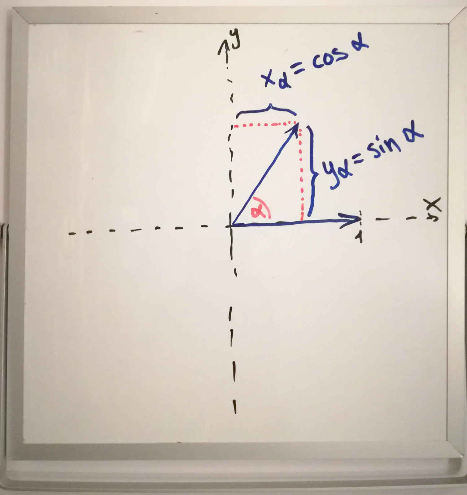
Since my trusty ‘hand-held’ whiteboard has been a nice help to visualize some concepts… here’s a very basic diagram.

Let’s look a bit further and assume we want to take our unit vector that’s been rotated by \(\alpha\) in a 2D plane and rotate it “out” of the plane by some angle \(0^\circ < \beta < 90^\circ\) towards the normal vector of the plane.

Let’s say our vector sat within the x/y-plane, but there’s also a z-axis:

$$\vec{v_\alpha} = \begin{pmatrix}\cos \alpha\\\sin \alpha\\0\end{pmatrix}$$

Now to rotate it by \(\beta\) we can look at \(x_\alpha\) and \(y_\alpha\) individually also being rotated up by \(\beta\).

$$x_\beta = x_\alpha \sin \beta\\y_\beta = y_\alpha \sin \beta$$

Here we use \(\sin\) in both cases because they’re both the adjacent side in their respective right-angled triangle: The side opposite from \(\beta\) is \(\vec{v_z} = \cos \beta\) in both cases, and the hypothenuse is \(x_\alpha\) and \(y_\alpha\) respectively.

That gives us our final vector on the hemisphere:

$$\vec{v} = \begin{pmatrix}\cos \alpha \sin \beta \\ \sin\alpha \sin\beta\\ \cos\beta \end{pmatrix}$$
The whiteboard illustration gets a bit messier for 3d&hellip;

The whiteboard illustration gets a bit messier for 3d…

This is basically just the formula for converting from spherical to cartesian coordinates!

Now let’s define some “helper” variables:

$$s = \sin\beta\\c = \cos \beta$$ $$\vec{v} = \begin{pmatrix}\cos(\alpha) \cdot s \\ \sin(\alpha) \cdot s\\ c \end{pmatrix}$$

Our regular three-dimensional vector space has the standard basis \({\vec{e_x} = (1, 0, 0)}\), \({\vec{e_y} = (0, 1, 0)}\), \({\vec{e_z} = (0, 0, 1)}\). With this basis we can write our vector as such:

$$\vec{v} = \vec{e_x} \cdot \cos(\alpha) \cdot s + \vec{e_y} \cdot \sin(\alpha) \cdot s + \vec{e_z} \cdot c$$

Looking back at the code we see this structure:

1
direction = Vector3(...) * cosf(p) * s + Vector3(...) * sinf(p) * s + normal * sqrtf(c);

With p in this case being a variable between \(0 \le p \le 2\pi\) just as \(\alpha\) above was any angle within a full circle! So where for my example I constructed a random unit vector on a hemisphere centered around \(\vec{e_z}\), in this case it seems to be centered around the normal pointing off our surface. So far so good.

So the remaining question just became: What are those magical vectors constructed in place of \(\vec{e_x}\) and \(\vec{e_y}\)? Clearly they must be forming a sort of standard basis to align the hemisphere around the normal.

And then there’s the question of c and s being constructed from something between 0.0f and 1.0f and sqrt() and stuff.

Sub-puzzle: Construct standard basis from normal

Before I show the code for the two new vectors, a quick reminder: Our constraint on this is still \(normal \in \{({\footnotesize\pm}1, 0, 0), (0, {\footnotesize\pm}1, 0), (0, 0, {\footnotesize\pm}1)\}\), which is quickly proven by reductio ad absurdum — if we assumed the code works for arbitrary unit vectors, we can try some random ones and look at the results:

Some matplotlib 3d graphs in a jupyter notebook.

Some matplotlib 3d graphs in a jupyter notebook.

It’s not looking good. I don’t have proof that all other vectors result in garbage, but these certainly aren’t at right angles.


Our “sub-puzzle” now looks like this:

 1
 2
 3
 4
 5
 6
 7
 8
 9
10
11
12
13
14
15
16
float g = n.z < 0 ? -1 : 1;
float u = -1 / (g + n.z);

float v = n.x * n.y * u;
float a = n.y * n.y * u;
float b = n.x * n.x * u;

Vector3 o(  v,
            g + a,
           -n.y
         );

Vector3 p( 1 + g * b,
               g * v,
              -g * n.x
         );

…which still does exactly the same thing as the code on the postcard, albeit with some cosmetic changes applied:

  • renamed normal to n
  • added float variables a and b, alongside v
  • the two vectors o and p as part of the basis \({\{\vec{n}, \vec{o}, \vec{p}\}}\)

Here’s three initial observations under the given constraint:

  • v = n.x * n.y * u = 0 always, because either n.x or n.y will be 0 in any case. This makes v obsolete and implies \(o_x = p_y = 0\)
  • u only gets used in v, a and b:
    • If \(n_z = {\footnotesize\pm}1\), we have a = b = 0 because n.x = n.y = 0, thus u does not matter.
    • If \(n_z = 0\), we have g = 1 and u = -1.
    • Thus we can set u = -1 for all uses, which is solely to negate a and b.
  • With \(n_x, n_y \in \{-1, 0, 1\}\) we get \(n_x n_x = |n_x|\) and \(n_y n_y = |n_y|\) allowing us to simplify a and b further, albeit not by much.

Applying all changes results in:

 1
 2
 3
 4
 5
 6
 7
 8
 9
10
11
12
13
float g = n.z < 0 ? -1 : 1;
float a = -abs(n.y);
float b = -abs(n.x);

Vector3 o(  0,
            g + a,
           -n.y
         );

Vector3 p( 1 + g * b,
               0,
              -g * n.x
         );

If g was always 1 we could at least drop it from p. The only other value of g = -1 occurs for \(\vec{n} = (0, 0, -1)\). In that case we know that \(n_x = 0 \implies b = 0\), which are the two variables g gets multiplied with in p — so we can conveniently assume that g = 1 always works for p, even at \(n_z < 0\).

In other words: g has no effect on p at all! I will also put a and b back into the vectors, since things are super simple now:

 1
 2
 3
 4
 5
 6
 7
 8
 9
10
11
float g = n.z < 0 ? -1 : 1;

Vector3 o( 0,
           g - abs(n.y),
          -n.y
         );

 Vector3 p( 1 - abs(n.x),
            0,
           -n.x
         );

These two look suspiciously similar now. I wonder if I can use g = 1 for all cases, or alternatively use g in place of the 1 within p?

Something that’s helped me a lot in figuring these connections and constraints out was to just write all the values down in a table for all six normal vectors. Let’s do that now:

$$\vec{o} = \begin{pmatrix}0\\g-|n.y|\\-n.y\end{pmatrix}$$
n.x n.y n.z g o.x o.y o.z
1 0 0 1 0 1 0
-1 0 0 1 0 1 0
0 1 0 1 0 0 -1
0 -1 0 1 0 0 1
0 0 1 1 0 1 0
0 0 -1 (-1) 0 (-1) 0
$$\vec{p} = \begin{pmatrix}1-|n.x|\\0\\-n.x\end{pmatrix}$$
n.x n.y n.z g p.x p.y p.z
1 0 0 1 0 0 -1
-1 0 0 1 0 0 1
0 1 0 1 1 0 0
0 -1 0 1 1 0 0
0 0 1 1 1 0 0
0 0 -1 -1 1 0 0

I’ve highlighted the values that go into each vector: n.y and g create \(\vec{o}\), while \(\vec{p}\) is made solely from n.x. Which is why the last four rows all result in \(\vec{p} = (1,\ 0,\ 0)\).

I’ve also especially highlighted the values of (-1) in the last row of the first table: This is the only point where g makes a real difference.

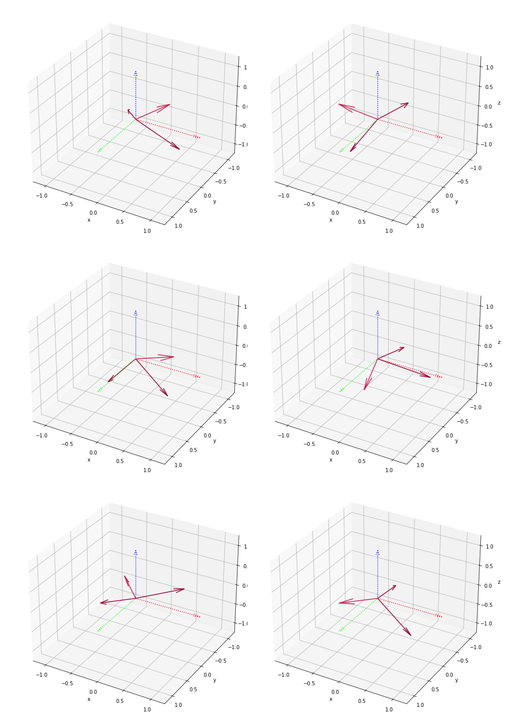
Now if I had to make a guess on why the vectors are constructed this way, it might be to preserve the “handedness” of the system we’re working in. Here’s a plot of all six sets of \((\vec{n}, \vec{o}, \vec{p})\):

Some matplotlib 3d graphs in a jupyter notebook.

Some matplotlib 3d graphs in a jupyter notebook.

def get_normals_for(nx, ny, nz):
    g = -1 if nz < 0 else 1
    o = (           0, g - abs(ny), -ny )
    p = ( 1 - abs(nx),           0, -nx )
    return o, p

And the python function used to get the normals; using code closer to the original involving g, u, v, gives the same result.

Now, if I’m not mistaken, the handedness or orientation of all the oriented vector spaces shown above is “right-handed”, just as I graphed the x/y/z axes in a right-handed way. Actually — hold on a minute. I was so focused on them being the same handedness, I didn’t even notice they’re all the opposite handedness of the original system!

I’m no expert on this, but I believe if I were to express these as linear mappings they’d all be some permutation of the axes along with mirroring one or two axes in some cases:

\( \begin{pmatrix} 0 \\ 0 \\ 1 \end{pmatrix}, \begin{pmatrix} 0 \\ 1 \\ 0 \end{pmatrix}, \begin{pmatrix} 1 \\ 0 \\ 0 \end{pmatrix} :\ \ \ f(x,y,z) = (z,y,x) \ \ \ \begin{vmatrix} 0 & 0 & 1\\ 0 & 1 & 0\\ 1 & 0 & 0 \end{vmatrix}=-1 \)
\( \begin{pmatrix} 0\\ 0\\ -1 \end{pmatrix} ,\begin{pmatrix} 0\\ -1\\ 0 \end{pmatrix} ,\begin{pmatrix} 1\\ 0\\ 0 \end{pmatrix} :\ \ \ f(x,y,z)=(z,-y,-x)\ \ \ \begin{vmatrix} 0 & 0 & 1\\ 0 & -1 & 0\\ -1 & 0 & 0 \end{vmatrix} =-1 \)
\( \begin{pmatrix} 0\\ 1\\ 0 \end{pmatrix} ,\begin{pmatrix} 0\\ 0\\ -1 \end{pmatrix} ,\begin{pmatrix} 1\\ 0\\ 0 \end{pmatrix} :\ \ \ f(x,y,z)=(z,x,-y)\ \ \ \begin{vmatrix} 0 & 0 & 1\\ 1 & 0 & 0\\ 0 & -1 & 0 \end{vmatrix} =-1 \)
\( \begin{pmatrix} 0\\ -1\\ 0 \end{pmatrix} ,\begin{pmatrix} 0\\ 0\\ 1 \end{pmatrix} ,\begin{pmatrix} 1\\ 0\\ 0 \end{pmatrix} :\ \ \ f(x,y,z)=(z,-x,y)\ \ \ \begin{vmatrix} 0 & 0 & 1\\ -1 & 0 & 0\\ 0 & 1 & 0 \end{vmatrix} =-1 \)
\( \begin{pmatrix} 1\\ 0\\ 0 \end{pmatrix} ,\begin{pmatrix} 0\\ 1\\ 0 \end{pmatrix} ,\begin{pmatrix} 0\\ 0\\ -1 \end{pmatrix} :\ \ \ f(x,y,z)=(x,y,-z)\ \ \ \begin{vmatrix} 1 & 0 & 0\\ 0 & 1 & 0\\ 0 & 0 & -1 \end{vmatrix} =-1 \)
\( \begin{pmatrix} -1\\ 0\\ 0 \end{pmatrix} ,\begin{pmatrix} 0\\ 1\\ 0 \end{pmatrix} ,\begin{pmatrix} 0\\ 0\\ 1 \end{pmatrix} :\ \ \ f(x,y,z)=(-x,y,z)\ \ \ \begin{vmatrix} -1 & 0 & 0\\ 0 & 1 & 0\\ 0 & 0 & 1 \end{vmatrix} =-1\\ \)

…I built those permutation matrices from staring at my graphs, and only after writing it all out like this I realized that putting \((\vec{n}, \vec{o}, \vec{p})\) side by side like that gives the exact same thing, since it essentially shows which part of the standard basis ended up where…

The \({\begin{vmatrix}...\end{vmatrix} = -1}\) is the determinant of the matrix, and according to Wikipedia a nonsingular linear mapping is orientation-preserving if its determinant is positive (see orientation linked earlier) and I’m inclined to believe them. Since all of these come out as -1 all of them have the opposite orientation to their input system.

So we’re not even keeping the orientation the same… and in any case it’s easy to see how how the orientation does not matter one bit for what we’re doing:

Our scalars for the second and third vector are \(\cos(\alpha)\cdot s\) and \(\sin(\alpha)\cdot s\) where \(\alpha\) is a random angle on a full circle, so the \(\sin\) and \(\cos\) are between -1 and 1… if we invert \(\vec{o}\) or \(\vec{p}\) we might be mirroring the hemisphere, but our vector is picked randomly within that hemisphere anyways!

It’s like using \({360^\circ-\alpha}\) instead of \(\alpha\), randomly picked from \(0^\circ \le \alpha \le 360^\circ\). Nothing really changes, it’s still a random angle.

So let’s do away with handedness and just pick the easiest “permutations” we can:

def get_normals_simple(nx, ny, nz):
    return (nz, nx, ny), (ny, nz, nx)
Some matplotlib 3d graphs in a jupyter notebook.

Some matplotlib 3d graphs in a jupyter notebook.

Let’s check out the determinant:

\( \begin{vmatrix} x & z & y\\ y & x & z\\ z & y & x \end{vmatrix} = x^3+y^3+z^3-yzx-xyz-zxy \)

Still assuming we input one of the six axis-aligned normals, we can drop the subtracted terms at the end: They’ll always be zero under those circumstances. And the terms in front have the same sign as the input vector has, i.e. the “negative” vectors get a basis of opposite orientation.

An easy fix (not that we need one!…) might look like this:

\( \begin{vmatrix} x & |z| & |y|\\ y & |x| & z\\ z & y & x \end{vmatrix} = x^2|x|+y^2|y|+z^2|z|-|x|yz-x|y|z-xy|z| \)

…or put the abs() on any single set of \(x,\ y,\ z\) in the matrix, it all yields the same determinant :)

But as we can see within the formula, each of them get squared, taking away the sign, and multiplied with their abs value. The latter three terms still drop away. So the determinant will always be 1. 1

It’s equally simple to make them all -1. But I think I’ve spent enough (read: entirely too much…) time thinking and writing about these vector system bases.

A copy of my Jupyter notebook used to explore these normal vectors and to get the matplotlib graphs can be viewed here as a Github Gist.

And if you head over to https://jupyter.org/try you can even spin up your own temporary jupyter-notebook server in a matter of minutes via the mybinder.org project without signing up, which seems almost too good to be true! After trying it out there I did end up switching to a local installation on my laptop.

I also added the vastly simplified vectors to the code base in this commit.

Trig vs. Pythagoras

Now, where did we leave things before investigating these normals?…

1
2
3
4
5
6
7
8
9
 float p = 6.283185 * randomVal();

 float c = randomVal();
 float s = sqrtf(1 - c);

 direction = Vector3(0, g - abs(normal.y), -normal.y) * (cosf(p) * s)
           + Vector3(1 - abs(normal.x), 0, -normal.x) * (sinf(p) * s)
           + normal * sqrtf(c);
 //[...]

Right, here. The vectors have been thoroughly picked apart — that leaves c and s to be inspected.

I’ve mentioned before that I would expect

$$s = \sin\beta\\c = \cos \beta$$

or something like this:

 1
 2
 3
 4
 5
 6
 7
 8
 9
10
 float p = 6.283185 * randomVal();
 float q = 1.5707963 * randomVal();

 float c = cosf(q);
 float s = sinf(q);

 direction = Vector3(0, g - abs(normal.y), -normal.y) * (cosf(p) * s)
           + Vector3(1 - abs(normal.x), 0, -normal.x) * (sinf(p) * s)
           + normal * c;
 //[...]

Where \(1 > c > 0\) and \(0 < s < 1\).

Thanks to the pythagorean theorem we could also say \(s = \sin q = \sqrt{1-\cos^2 q} = \sqrt{1-c^2}\) which was almost there but not quite. And why the use of sqrt(c) in place of c, originally?

This bit was still a mystery to me, and I almost left it at that; assuming it’s just close enough to the \(\sin\) and \(\cos\) of a random angle under \(90^\circ\)

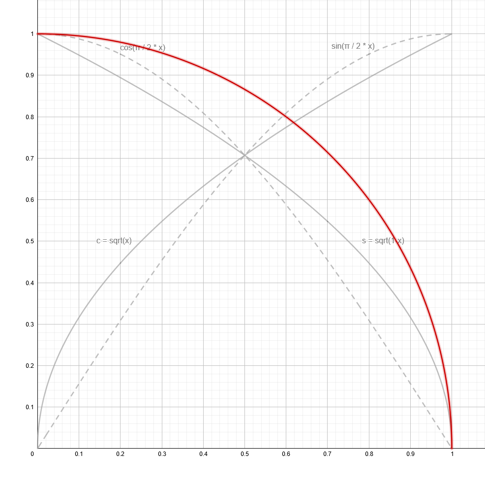
Almost. But then I went and took another look at it with the help of some Geogebra graphs:

top: sin(x*π/2) and cos(x*π/2)
middle: top &amp; bottom combined
bottom: sqrt(x) and sqrt(1-x)

top: sin(x*π/2) and cos(x*π/2)
middle: top & bottom combined
bottom: sqrt(x) and sqrt(1-x)

These look somewhat similar and even all cross through the exact same point at \(\sqrt{1-0.5} = \sqrt{0.5} = \frac{\sqrt{2}}{2} = \sin{\frac{\pi}{2}0.5} = \cos{\frac{\pi}{2}0.5}\). What’s the deal with all this? I wasn’t quite seeing the connection yet, until I plotted arcs using each set of functions as (x, y) coordinates:

You can play around with this on Geogebra here

You can play around with this on Geogebra here

Both methods form a perfect (quarter-)circle! Which should’ve been obvious when looking at the radii of these circle arcs:

$$\begin{aligned}\sqrt{x}^2 + \sqrt{1-x}^2 = x + 1 - x &= 1\ &\ \forall\ 0 \le x \le 1\\\sin^2{\frac{\pi}{2}x} + \cos^2{\frac{\pi}{2}x} &= 1\ &\ \forall\ 0 \le x \le 1\end{aligned}$$

The latter of which is the Pythagorean trigonometric identity.

So these two look the same, and yet they have a subtle difference. If I animate a vector that goes along the sin/cos-defined circle I get a constant speed of movement — the angle of the vector is directly proportional to x.

I should really try to implement or embed this interactively, but here’s a webm video.

For c and s however, as defined earlier, here’s where it points to:

Another webm. Different content.

A few notes on this:

  • I chose to draw the new vector w from the center of the previous vector v for illustrative purposes. I could’ve drawn it from (0, 0) and it would’ve looked like the other vector, except that it speeds up towards the center and slows towards the edges.
  • I also modified the rate of change for x here. Instead of moving at constant speed as before, x slows down towards the edges too.

The second change is because I wanted to highlight how close v gets to the axis before w gets anywhere near it.

So if we choose a uniformly random value \(0 \le x \lt 1\) and generate a vector with \(\sin\) and \(\cos\) it should also be uniformly distributed — all angles between \(0 - 90^\circ\) are equally likely.2

With the \(\sqrt{x}\) and \(\sqrt{1-x}\) method however we’re substituting a squared variable with x, essentially taking the square root of our uniform distribution which affects said distribution. Suddenly values in the middle are more likely and the ones at the edges are increasingly less likely as it is approached.

Viewed geometrically, the random number is used as the area of one of the squares that make up the pythagorean theorem’s triangle.

And I believe now that this is intentional! When bouncing a ray off a surface randomly it makes sense that a new ray shouldn’t be perfectly parallel to the surface, and bouncing them off at a perfect \(90^\circ\) might also cause issues, although those are probably less likely, and this is all speculation.

There’s a clearly visible difference between the two methods:

top: original renderer
middle/bottom: using cosf/sinf for c/s
256 samples @ 320x180px

top: original renderer
middle/bottom: using cosf/sinf for c/s
256 samples @ 320x180px

Out of curiosity I rendered another version with the ceiling planks aligned the other way — it seems like the repeating pattern on the floor is related to that.


I’m neither a statistician nor a data scientist, but that didn’t stop me from playing around with scipy in my jupyter-notebook for a bit:

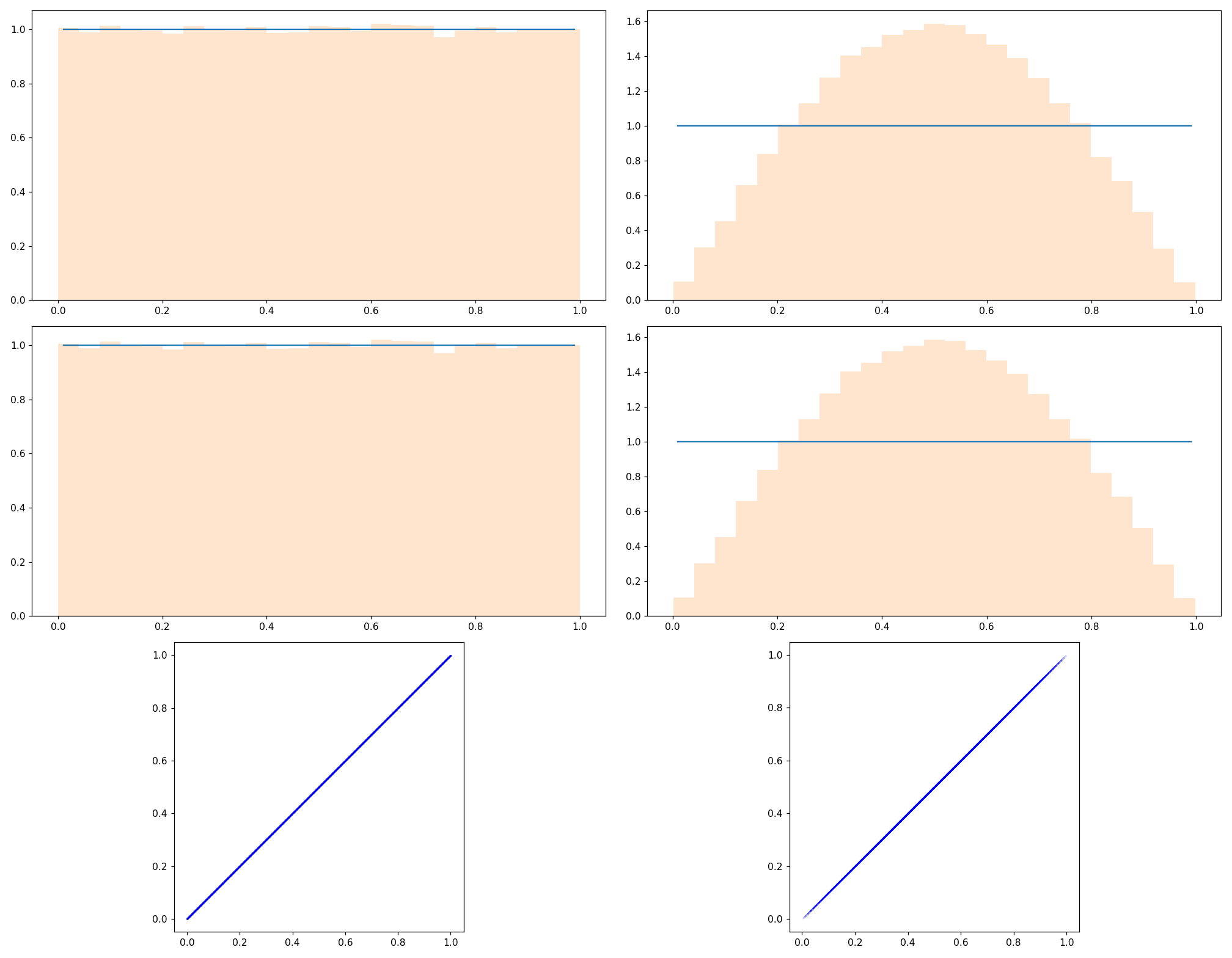
Here’s the gist of how I got my 100.000 sample values:

 1
 2
 3
 4
 5
 6
 7
 8
 9
10
11
12
13
14
15
16
17
def random_angled_normal_2d():
    u = rnd.random() * math.pi/2.0
    return normalize(vec( (sin(u), cos(u), 0) ))

def random_sqrt_normal_2d():
    r = rnd.random()
    s, c = sqrt(r), sqrt(1.0-r)
    return normalize(vec( (s, c, 0) ))

samples_x = []
samples_y = []

for i in range(1,100000):
    r = random_angled_normal_2d()
    r = random_sqrt_normal_2d()
    samples_x.append(arccos(r[0])*2/math.pi)
    samples_y.append(arcsin(r[1])*2/math.pi)

Commenting out either line 14 or 15 to for the left/right graphs above.

In the last two lines you can see how I essentially do the inverse of what random_angled_normal_2d() did to the random numbers — so it is not surprising at all that I plot a uniform distribution in that case. I hope my approach here is not flawed. Doing the same to the “sqrt” method gives the polynomial(?) looking distribution.

And my jupyter notebook file for these can be viewed here as a Github Gist once again.

There’s some other nonsense in there where I tried to contour plot the samples as a multivariate normal distribution, until I accepted that I had no idea what I was doing. Even the use of the scatter plot seems questionable at best.


Not much has changed within the code, this post was more of a deeper exploration of what exactly happens within Trace().

I’m pretty glad I’m getting this out though, with this I’ve accomplished most of what I set out to write about. I had hoped to get this done within 2020 but it took me most of Jan 2021 as well, between winding down over christmas and work picking back up afterwards.

Following this I could still look further into the tone mapping being used. And I’m really tempted to ditch Urho3D in favor of just using GLEW/Glfw3 + glm or Eigen, and a single header png writer.

— Final(?) results —

Once more I’m embedding the entire body of code, minus the Urho3D scaffolding:

 17
 18
 19
 20
 21
 22
 23
 24
 25
 26
 27
 28
 29
 30
 31
 32
 33
 34
 35
 36
 37
 38
 39
 40
 41
 42
 43
 44
 45
 46
 47
 48
 49
 50
 51
 52
 53
 54
 55
 56
 57
 58
 59
 60
 61
 62
 63
 64
 65
 66
 67
 68
 69
 70
 71
 72
 73
 74
 75
 76
 77
 78
 79
 80
 81
 82
 83
 84
 85
 86
 87
 88
 89
 90
 91
 92
 93
 94
 95
 96
 97
 98
 99
100
101
102
103
104
105
106
107
108
109
110
111
112
113
114
115
116
117
118
119
120
121
122
123
124
125
126
127
128
129
130
131
132
133
134
135
136
137
138
139
140
141
142
143
144
145
146
147
148
149
150
151
152
153
154
155
156
157
158
159
160
161
162
163
164
165
166
167
168
169
170
171
172
173
174
175
176
177
178
179
180
181
182
183
184
185
186
187
188
189
190
191
192
193
194
195
196
197
198
199
200
201
202
203
204
205
206
207
208
209
210
211
212
213
214
215
216
217
218
219
220
221
222
223
224
225
226
227
228
229
230
231
232
233
234
235
236
237
238
float randomVal() { return (float) rand() / RAND_MAX; }

// Box CSG equation. Returns minimum signed distance from space
// carved by start vector and opposite corner vector end.
class BoxTester {
public:
    Vector3 start;
    Vector3 end;

    BoxTester(Vector3 b, Vector3 e) : start(b), end(e) {}

    float Test(Vector3& position)
    {
        Vector3 toLowerLeft = position - start;
        Vector3 toUpperRight = end - position;

        return -std::min( // <- minimum distance out of all, i.e. to closest wall of the box
                    std::min( // <- minimum distance on x- OR y-axis
                        std::min(toLowerLeft.x_, toUpperRight.x_),  // <- minimum distance on x-axis
                        std::min(toLowerLeft.y_, toUpperRight.y_)   // <- minimum distance on y-axis
                    ),
                    std::min(toLowerLeft.z_, toUpperRight.z_)       // <- minimum distance on z-axis
                );
    }
};

// Lower room (the room itself)
BoxTester box_room(Vector3(-30, -.5, -30), Vector3(30, 18, 30));
// Upper room (The space where the ceiling planks are)
BoxTester box_roof(Vector3(-25, 17, -25), Vector3(25, 20, 25));
// Ceiling "planks", or one of them. Actual tested position will be modulo'd along an axis.
BoxTester box_planks(Vector3(1.5, 18.5, -25), Vector3(6.5, 20, 25));

#define HIT_NONE 0
#define HIT_LETTER 1
#define HIT_WALL 2
#define HIT_SUN 3

class LetterLine {
public:
    const Vector2 start;
    const Vector2 end;
    const Vector2 direction;
    const Vector2 normal;
    const float length;

    LetterLine(Vector2& b, Vector2& e) : start(b), end(e),
                                         direction(e - b),
                                         normal(direction.Normalized()),
                                         length(direction.Length())
    {}
};


std::vector<int> pixar_points = {
         -13, 0,  -13, 8, // P stem
         -13, 4,  -11, 4, // P top bar
         -13, 8,  -11, 8, // P mid bar

          -7, 0,   -5, 0, // I bottom bar
          -6, 0,   -6, 8, // I stem
          -7, 8,   -5, 8, // I top bar

          -3, 0,    1, 8, // X slash
          -3, 8,    1, 0, // X backslash

           3, 0,    5, 8, // A slash
           5, 8,    7, 0, // A backslash
           4, 4,    6, 4, // A bar

           9, 0,    9, 8, // R stem
           9, 4,   11, 4, // R mid bar
           9, 8,   11, 8, // R top bar
          10, 4,   13, 0  // R leg
        };

std::vector<LetterLine> letterlines = {};

// Two curves (for P and R in PixaR) with hard-coded locations.
// curve centers are between right ends of the bars.
std::vector<Vector2> curve_centers = {
  Vector2(-11, 6),
  Vector2( 11, 6)
};

Vector3 camera_position = Vector3(-22, 5, 25);
Vector3 lookat_position = Vector3(-3, 4, 0);
Vector3 light_direction = Vector3(.6, .6, 1);

void SetupPathtracer() {

    for (int i = 0; i+3 < pixar_points.size(); i += 4) { // letters.Length()
        //Vector3 begin = Vector3(letters.At(i) - 79, letters.At(i+1) - 79);
        //Vector3 end = Vector3(letters.At(i+2) - 79, letters.At(i+3) - 79);
        Vector2 b = Vector2(pixar_points[i  ], pixar_points[i+1]);
        Vector2 e = Vector2(pixar_points[i+2], pixar_points[i+3]);

        LetterLine* l = new LetterLine(b, e);
        letterlines.push_back(*l);
    }
}


// Sample the world using Signed Distance Fields.
float QueryDatabase(Vector3 position, int &hitType) {
    float distance = 1e9;
    Vector2 pos_in_z0(position.x_, position.y_); // Flattened position (z=0)

    for (LetterLine line : letterlines) {
        // factor to scale line.normal by to project position onto line
        // i.e. with this factor alone (line.start + line.normal * scale_factor)
        // gives us the closest point on an infinite line
        float scale_factor = Vector2(pos_in_z0 - line.start).DotProduct(line.normal);

        // But now we clamp the scaling within 0.0f <= scale_factor <= line length
        scale_factor = std::min(std::max(scale_factor,  0.0f), line.length);

        Vector2 letter_distance = pos_in_z0 - (line.start + line.normal * scale_factor);

        distance = std::min(distance, letter_distance.Length()); // compare distance.
    }

    for (Vector2 c : curve_centers) {
        Vector2 center_to_pos = pos_in_z0 - c;

        if(center_to_pos.x_ > 0) {
            float comparison_dist = std::abs(center_to_pos.Length() - 2.0f);
            distance = std::min(distance, comparison_dist);
        }
    }

    distance = powf(powf(distance, 8) + powf(position.z_, 8), .125) - .5;
    hitType = HIT_LETTER;

    Vector3 plank_test_pos(position);
    plank_test_pos.x_ = fmodf(fabsf(plank_test_pos.x_), 8.0f);

    float roomDist = std::min(// min(A,B) = Union with Constructive solid geometry
                        //-min carves an empty space
                        -std::min(
                             box_room.Test(position), // Lower room
                             box_roof.Test(position) // Upper room
                        ),
                        box_planks.Test(plank_test_pos) // Ceiling "planks" spaced 8 units apart.
                    );
    if (roomDist < distance) distance = roomDist, hitType = HIT_WALL;

    float sun = 19.9 - position.y_ ; // Everything above 19.9 is light source.
    if (sun < distance)distance = sun, hitType = HIT_SUN;

    return distance;
}

// Perform signed sphere marching
// Returns hitType 0, 1, 2, or 3 and update hit position/normal
int RayMarching(Vector3 origin, Vector3 direction, Vector3 &hitPos, Vector3 &hitNorm) {
    int hitType = HIT_NONE;
    int noHitCount = 0;
    float d; // distance from closest object in world.

    // Signed distance marching
    for (float total_d=0; total_d < 100; total_d += d) {
        hitPos = origin + direction * total_d;
        d = QueryDatabase(hitPos, hitType);

        // negative distance will mean we're inside the object we hit, I guess
        // and we'll return right away so no worries there
        if (d < .01 || noHitCount > 99) {
            int unusedReturnRef = 0;
            hitNorm = Vector3(QueryDatabase(hitPos + Vector3(.01, 0, 0), unusedReturnRef) - d,
                              QueryDatabase(hitPos + Vector3(0, .01, 0), unusedReturnRef) - d,
                              QueryDatabase(hitPos + Vector3(0, 0, .01), unusedReturnRef) - d).Normalized();
            return hitType;
        }
        ++noHitCount;
    }
    return 0;
}

Vector3 Trace(Vector3 origin, Vector3 direction) {
    Vector3 sampledPosition(1, 1, 1);
    Vector3 normal(1, 1, 1);
    Vector3 color(0, 0, 0);
    Vector3 attenuation(1, 1, 1);
    Vector3 lightDirection(light_direction); // Directional light
    lightDirection.Normalize();

    for (int bounceCount = 3; bounceCount--;) {
        int hitType = RayMarching(origin, direction, sampledPosition, normal);
        if (hitType == HIT_NONE) break; // No hit. This is over, return color.
        if (hitType == HIT_LETTER) { // Specular bounce on a letter. No color acc.
            direction = direction + normal * ( normal.DotProduct(direction) * -2);
            origin = sampledPosition + direction * 0.1;
            attenuation = attenuation * 0.2; // Attenuation via distance traveled.
        }
        if (hitType == HIT_WALL) { // Wall hit uses color yellow?
            float incidence = normal.DotProduct(lightDirection);
            float p = 6.283185 * randomVal();
            float c = randomVal();
            float s = sqrtf(1 - c);
            direction = Vector3(normal.y_,
                                normal.z_,
                                normal.x_) * (cosf(p) * s)
                      + Vector3(normal.z_,
                                normal.x_,
                                normal.y_) * (sinf(p) * s)
                      + normal * sqrtf(c);
            origin = sampledPosition + direction * .1;
            attenuation = attenuation * 0.2;
            if (incidence > 0 &&
                 RayMarching(sampledPosition + normal * .1,
                             lightDirection,
                             sampledPosition,
                             normal) == HIT_SUN)
                color = color + attenuation * Vector3(500, 400, 100) * incidence;
        }
        if (hitType == HIT_SUN) { //
          color = color + attenuation * Vector3(50, 80, 100); break; // Sun Color
        }
    }
    return color;
}

This time I’m skipping the relevant part of main() since it’s unchanged since last post.

(full main.cpp here)


As always, thank you for reading along.

If you have any corrections, constructive criticism or comments, please post them in the comments section below, or write to me via e-mail or Twitter! Feedback highly welcome. Stay safe out there.

~rf


  1. …I still have the urge to note on any of these statements, that it still only holds for \(x, y, z\) being some permutation of \(\pm1, 0, 0\)). ↩︎

  2. I’m going to ignore the fact that RNGs typically exclude the value of 1 itself… ↩︎